PowerControl Project
Smart Home project for controlling of devices at home
This project was a project of my school. It has an impact to "Raspberry Pi Backup Server" and "Stratoflights 2019". But this project was made in a time were I was a teenage and in school. This couse that the Code and other things are not perfect and not well thought out. Also it has not a good code style. On the other side there are some interesting thoughts made. So I choose to show it here. This project is like the already established thing what you can buy as smart socket. But the creation of such products the project I made here is not related.
The project of my school
In a school (school type of Berlin which offers after the main grades education sometime combined with apprenticeship) I done a part of my apprenticeship. Here we lerned much about IT, electronics and networks. This was focused in my apprenticeship. And every year this school had an open day. On this day each course shows something to interest visitors for a apprenticeship at the school. Our teachers had the idea, since the school had bought Raspberry Pi's and Arduinos and also the Smart Home was topically, we pupil shold do some projects with such a hardware for this topic. The base idea was just to use a Raspberry Pi or an Arduino to control something. The work on the project shold be done in the lessons and end in a mark on the school certificate. I done this project with a classmate. We started with the project in November 2015 and had time until Feburary 2016. In this month were the open day. At this day we shold present our project work not only to classmates, also to the visitors.
The basic idea of the project
The idea was to make something with a Raspberry Pi or an Arduino. I think a Arduino which is just a microcontroller is the best use for control or measure something. And the Raspberry Pi is better for the use as a Webserver as the centrum of anything I think. For Smart Home it is often an interest to switch something on and off but even smart. Or another intention is to have a look to something. For doing this the Arduino is a good option. But the user just want to do all settings or view all data at most on smartphone or maybe on computer. For this are application systems better which are running on a Raspberry Pi. It also can control something. But got the idea to make a system what is nowadays compareable to ZigBee. Many sensor and actuator units around and a central installed computer which is used manage any functions. There can be a Arduino connected between a socket and a device like a television or a fridge which can be used for switching with a relay or measuring of voltage and current. The measure will be made to watch the energy consumption. In the example the television can be switched when no one is at home. For viewing and calcualting the energy consumption over a year all Arduinos shold send thier data to the Raspberry Pi which can process them. Also can the user do the setup there.
The first prototype
Measurement of the consumed power
As we wanted to measure voltage and current to calculate the power we had to consider how to do it. The Arduino shold work as a controller for the measuring. It has a analog interface. While voltage and current are analog values it was
clear that we have to use the analog interface. But the Arduino by it self can only use the interface for TTL voltages. And we had planed to do the measureing next to the socket respectively conntect it between socket and device to do
measures or switch. There we have 230 Volts AC. Also some devices emit higher currents. This can not be measured with the analog interface of the Arduino.
After a longer search in the internet we found a example as shown in the picture. It uses a special controller to do the measure of the current in the devices circuit and sends the value as a analog value to the Arduino. The voltage gets
direct taken from a voltage divider circuit. Unfortunately we found that the measure controller is not easy to buy. Also we can not find instructions for it.
I think that the value of the current will be send as a voltage factor of a reference voltage to the Arduino. This means we have to convert it to the real current value. The voltage has to be converted while it is measured after the voltage
divider. As you can see in the picture, the example things on a measure at 24 volts (probably in DC) and we wanted to do the measure at 230 volts. As we dont't have all required things we just have made switching of devices.
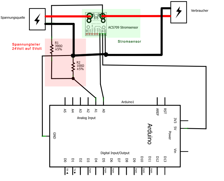
Measure circuit from an example
A easy switching function done with the Arduino
To make a light control with the system we had considered, it was one thing to switch with the Arduino. It's just a very basic task. Every Aduino switching module shold be toggled by the server. Or else it doesn't make sense. Our server is
the "brain" and controlls anything with a timer. Und as drawn in the example for switch the light we have to use an Arduino to switch automated. If we do the switch next to the socket the user can not switch directly anymore if it
currently switched off by the system. And the idea, to have to open the website for telling the Arduino it has to switch in any way, we thought it is not a good idea to make it like this. So we thought that it will be better that the
Arduino can be triggered to switch from remote (from the server) and direct when the user pushes a button.
So we just made a first design for switch at the Arduino. In the picture you can see a LED that is connected to the Arduino. It can after the design be replaced with a bigger lamp for the socket (also if that will require a seperate
circuit). The push button which is connected over a resistor can be used to toggle the device state directly. It can later be replaced with another key (for example a wall button). So the user can then switch direct if he need it or the
system if it got the command from the server.
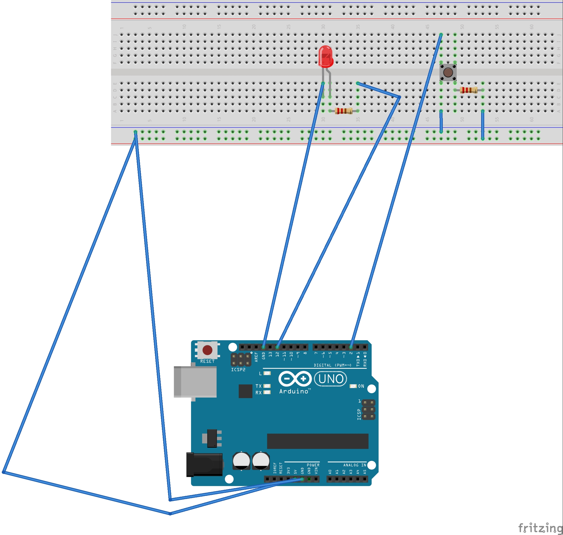
Primitive sketch of the Arduino switching circuit
Connection of the Arduino with the Raspberry Pi
To let the devices been controlled remotely from the server, I ask me how can I do that. The Raspberry shold be the central server. So it has to connect to the Arduinos. It must be done by a free type of communication. For example Low
Frequency Radio segment or existing networks like WLAN. But the time goes on and the required components were missing. Also we saw examples how to use the ESP8266 to connect an Arduino to the WLAN. But for this we don't have enough
knowledge.
When I go through the examples of the Arduino IDE I found the "SerialEvent" sketch from the developer Tom Igoe. It shows the usage of the serail interface of the Arduino. It can be used with the Tx/Rx pins on the digital connector
or with the USB port. Alright - and now you can just connect the Arduino with the USB cable to the Raspberry Pi. If you then transfer the code of the "SerialEvent" sketch with the IDE to the Arduino you can after that open the
"SerialMonitor" and see when you enter a message that it will be send back to the terminal.
This was the alternative for us to build a prototype which is direct connected to the Raspberry Pi. For testing the use of the serial connection without the IDE we written a small python script. And now when the Arduino recives a 1 or a 0
it switches the LED on or off. So we can at this moment control the device directly and "remote" on the Arduino.
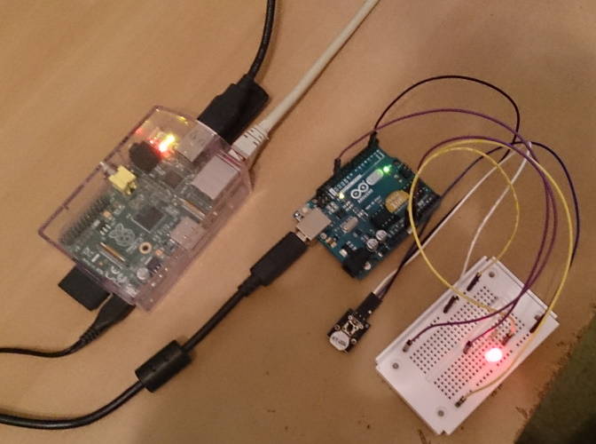
A photo of a prototype with a LED as a device to switch connected to a Arduino UNO R3. It is also connected to a Raspberry Pi and gets from there managed.
A Protocol is required for the comunication
We wanted beside the switching function to query the measurement of the power to store the value on the server. This was a important point that we can calculate the engergie costs about the calender year.
We also wanted that the user can set that the light will switch on or off at a defined time. A also important thing is that the user can check the setting in the server.
So I got the idea to create something like a protocol for the comunication of both systems. I defined that there are a list of commands that are particular expanded with arguments. Also the were codes for returning information.
On the Arduino there must be programmed then a keyword split. Helpful is that the spoken on SerialEvent code waits util a whole string is transmitted. So I had only to cut the recived string and then branch out the code depending on the keyword. Every time the Arduino had to return something. In minimum if it process the command successfully, if it was not successful or if it don't know the send command. If the system requested a info with a keyword which specifies which info was requested, the controller answered even then with the information.
The kewords which are defined in the protocol were defined to four character. A programm on the Raspberry Pi has then to decode the strings in human readble information. Or it has to encode the required commands to these shortnings that the user dosn't need to have the knowledge about them.
Command codes (to send ending with \0 ):
| Command chain | Description |
|---|---|
| setA | Activate Device |
| setI | Deactivate device |
| setT <TIME_NOW FORM(HH_mm_ss)> <TIME_TICK FORM(HH_mm)> (dact | nact) | At declared time switch, with 1) current time, 2) switching time, 3) (De-)Activate |
| info (stat | lght | powr | time) | Status info for Device state | light value at sensor | current power at sensor | setting of timer |
Returning codes (recive with \n):
| Returning values | Description |
|---|---|
| done | Command executed with no errors |
| secf | Can't execute - Security shutdown |
| echo devc (iact | nact) | Show if the device is currently active |
| echo lght (nght | dayL | dayS | dayC) | Query for the light class using a enum type |
| echo powr <var> | Output of the current electrical power |
| echo time (iact | nact) + <HH_MM> | Output if timer is (activated | deactivated) is and time value. If it is deactivated the time is even 00:00 |
| fail | Not possible! Device is already in the requested state |
| ncom | Unknown command |
A Website for the user to manage anything
With the defined protocol it was possible to comunicate between Raspberry Pi and Arduino. The Python script already make it possible to send and recive commands. But this is for the daily user it is not the best way. Also there was not
enough time to make an app, so there must be a website. Now it was time for the Raspberry Pi. On it the comunication works fine. Now we installed a webserver and a scripting environment on it. We used the Apache webserver. Unfortunately we
don't know at this time if the Apache webserver can run python scripts. But we also know, how to let run a script by PHP which is stored in the webserver.
So we have written mutiple Python scripts for each action. These had combined the needed parameters (some were collected from HTML) and then it called the Python script with the parameters. This caused then that the parameters were send via
the USB serial interface to the Arduino which then can split the keywords and do the actions. When the Arduino returns something the Python script records it and returns it to the PHP script. There it can be handled, transformed into a
human readable information and output to the website. By clicking on the on- or off- function the user can now sit on a sofa with the smartphone in his hand and can switch on the lights and set it to switch off at midnight.
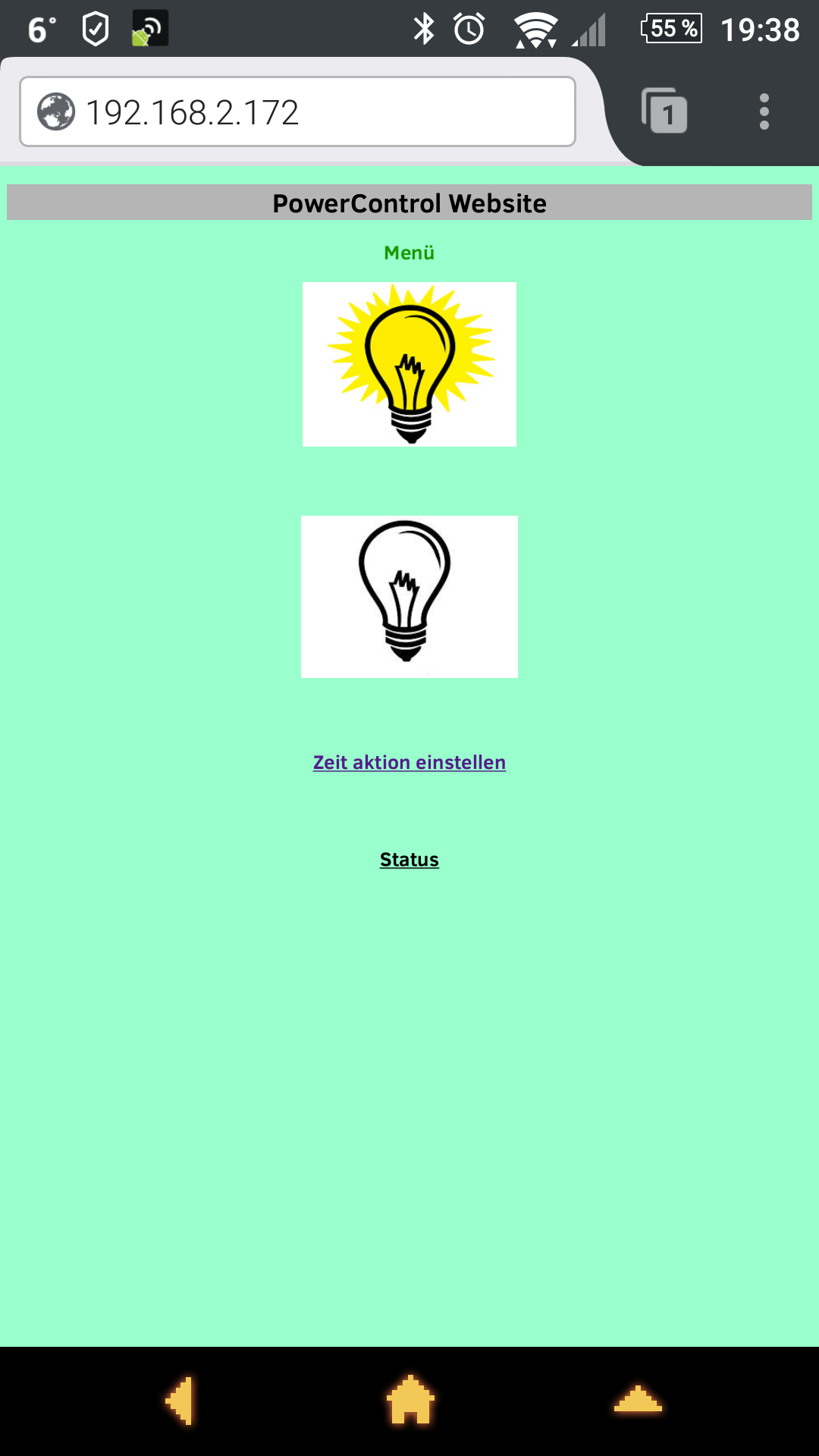
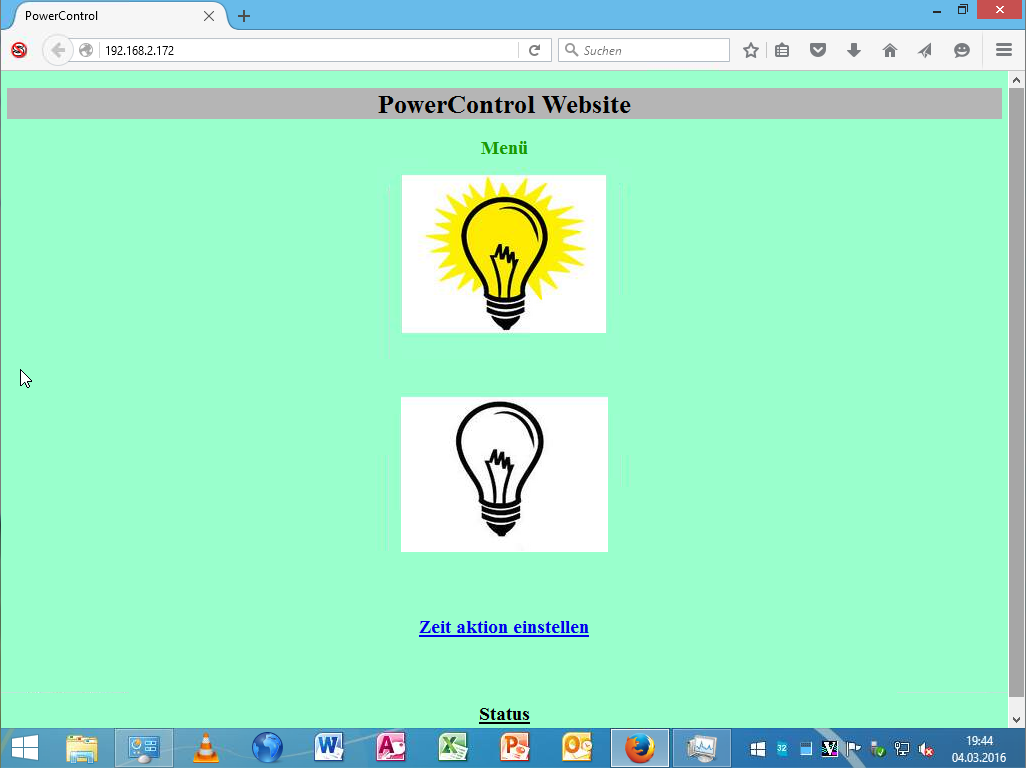
These pictures show the Web front end which the user can use to manage the system. One time called from an Android smartphone and one time called from a computer.
Presenting the project
At the end was the presentation at the open day. Up to this day it was passible to control, a lamp directly and remote. I installed the Raspberry Pi in the presentation room and connect it to the hotspot of my smartphone. Also I took my laptop with me and connted it also to the hotspot. I had done this all, because I wanted to show, that I can use the smartphone and my notebook to control anything over the website. At this day there were some people. I can remember that I talked with an older man about the project and the thinkable features for the future ( I also think, that this man was only for his personal technical interests there :-D ).
Things which were not developed
What not had been developed is on the one hand the measuring of electrical power. We not build the measure circuit because the sensor is not easy to buy and it also can not be used at mains voltage. Therefore we can't measure voltage and
current to calculate the power and send it back to the server (if it get requested of it).
On the other hand we never deeper thought about the measurement of light. The protocol has the option for it. And also we planned that is a good idea to make a light controlling depending on the day light situation. But while the time in
the school year was missing, we not developed this feature. But maybe this is a part, which is easyer to develop in future.
Things which were maybe developed in future
While the Raspberry Pi and the Arduino are all time connected via USB cable, of corse one next step is to change the connection from wired to wireless.
If this is done, there is one big point to be changed. The project was done using an Arduino UNO. But the Arduino shold be installed at next to the power cord or direct into the housing of a socket to improve switching. And maybe it is
possible that also the measurement of power will fit into the housing. But the UNO is to big for this. The project must be in minimum ported to an Arduino Nano or better to a stand alone microcontroller installed on a own minimal PCB. Going
on if it is done, there can be mutiple such systems. These all cannected to the Raspberry Pi and managed by it. Then it is possible to control and / or measure all consuming devices. This is maybe the solution that the user can save mony
for energie. And maybe then there also is a daylight influenced light control.